Toon Outlines in Blender
17 Jul 2023
This is a quick post about implementing a classic trick to get black outlines – a duplicate object or extrusion with inverted surface normals. This little trick has been employed by countless CG artists and game devs to add a little bit of toon-iness. Here’s the contents of this post:
- Show how to accomplish this effect via the UI in Eevee. Thanks to the robust Blender community, that information is accessible all over the internet.
- Show how to get the same effect set up via code
- Tweaks required to get it working in Cycles.
- Discuss some of the related computer graphics concepts
I recently used this technique on a set of freelance animations I did for the Illinois State Geologic Survey, which you can check out on my animation page.
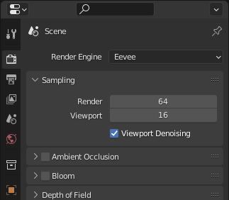
EEVEE UI SETUP: In the ‘Render Properties’ tab of the Properties panel, switch the Render Engine to Eevee.
In the ‘Modifier Properties’ tab of the Properties panel, click ‘Add Modifier’, and select ‘Solidify’ from the dropdown.
Create a material to use for your outlines. For this example, I used a black emission shader material.
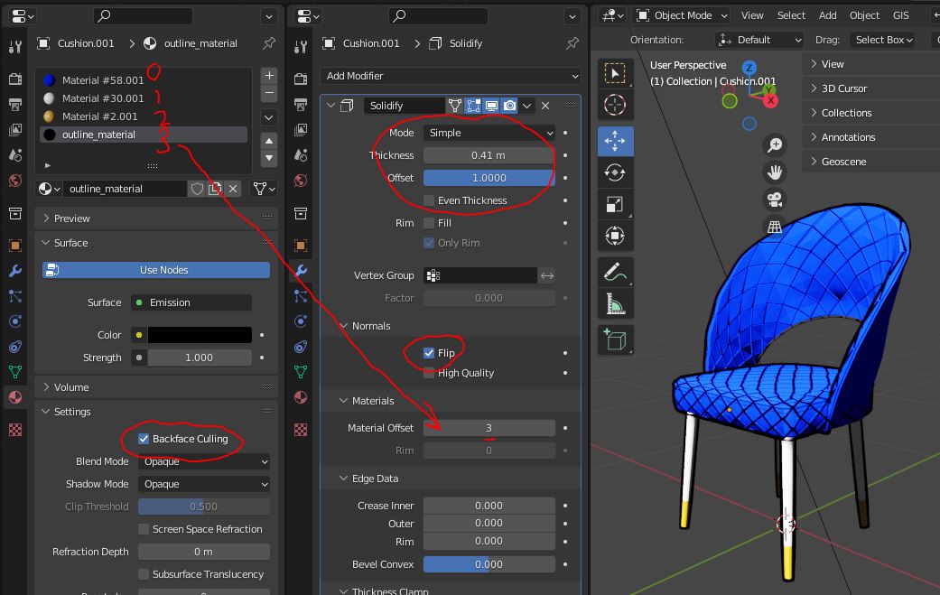
Set the material/modifier settings as highlighted in the below image. Play around with the Thickness, Offset, and Rim settings in the modifier until you get what you want. In ‘Material Offset’, put whatever number 0-index number your material is in your material slots. Mine is #3. The important settings and ‘Flip’ in the modifier and ‘Backface Culling’ in the materail.
Going through the process for dozens of objects would be tedious.
CODE: Let’s take a look at some code that can do the same thing. Here’s two functions, one that will put a material on an object and one that will add the solidify modifier and set some settings
For this script, I had a logger, calls on which I’ve left in below.
def apply_material_to_object(obj, mat, slot=0, setActive=True):
    thisLogger.info("Applying %s material to %s" % (mat, obj))
    if len(obj.material_slots) <= slot:
        thisLogger.info("Creating material slot")
        obj.data.materials.append(mat)
        obj.material_slots[slot].material = mat
    else:
        thisLogger.info("Putting in slot 0")
        obj.material_slots[slot].material = mat
    if setActive:
        obj.active_material_index = slot
    return

def add_solidify_outlines(obj, offset=1):
    sldfy = obj.modifiers.new("solidify", type = "SOLIDIFY")
    sldfy.use_flip_normals = True
    sldfy.thickness = .1
    sldfy.offset = 1.0
    sldfy.material_offset = offset
    return
Here’s how I used these functions. In the context in which I used this code, I wanted outlines applied to objects within a few different collections. I also had an outline material that already existed in my scene.
#Add the outlines
#This could be improved in the future by adding code to check whether outline is in mat slot 1
outlineMat = bpy.data.materials['outline_mat']
outlineCollections = ['nohighlight', 'highlight_geo', '2d_shadows']
for c in outlineCollections:
    for o in bpy.data.collections[c].objects:
        apply_material_to_object(o, outlineMat, slot=1, setActive=False)
        add_solidify_outlines(o)
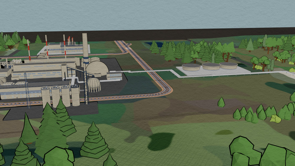
I used this code to apply the outlines to hundreds of objects at once, and then manually tweaked the settings to art-direct the shot. Here is an example of the results:
CYCLES TWEAKS: Backfacing culling doesn’t work the same way in Cycles, but you can still get this setup to work by making a seperate, duplicate object and doing backface culling through the outline material.
Duplicate the object.
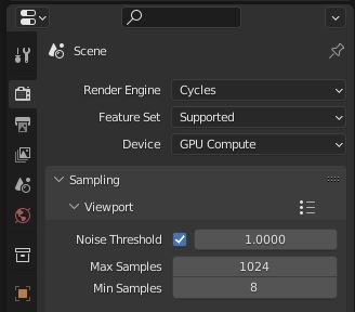
In the ‘Render Properties’ tab of the Properties panel, switch the Render Engine to Cycles.
Create a material to use for your outlines and put it in the first slot of the duped object. Go to the Shader Editor panel, and create the following node setup:
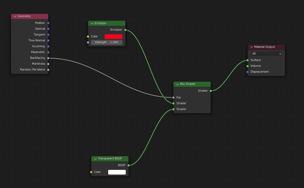
This setup will render a material in which the poly is shaded transparent if it’s facing back to you, and red emission if it’s facing front.
Add the Solidify outliner, and this time use ‘Complex’ mode.
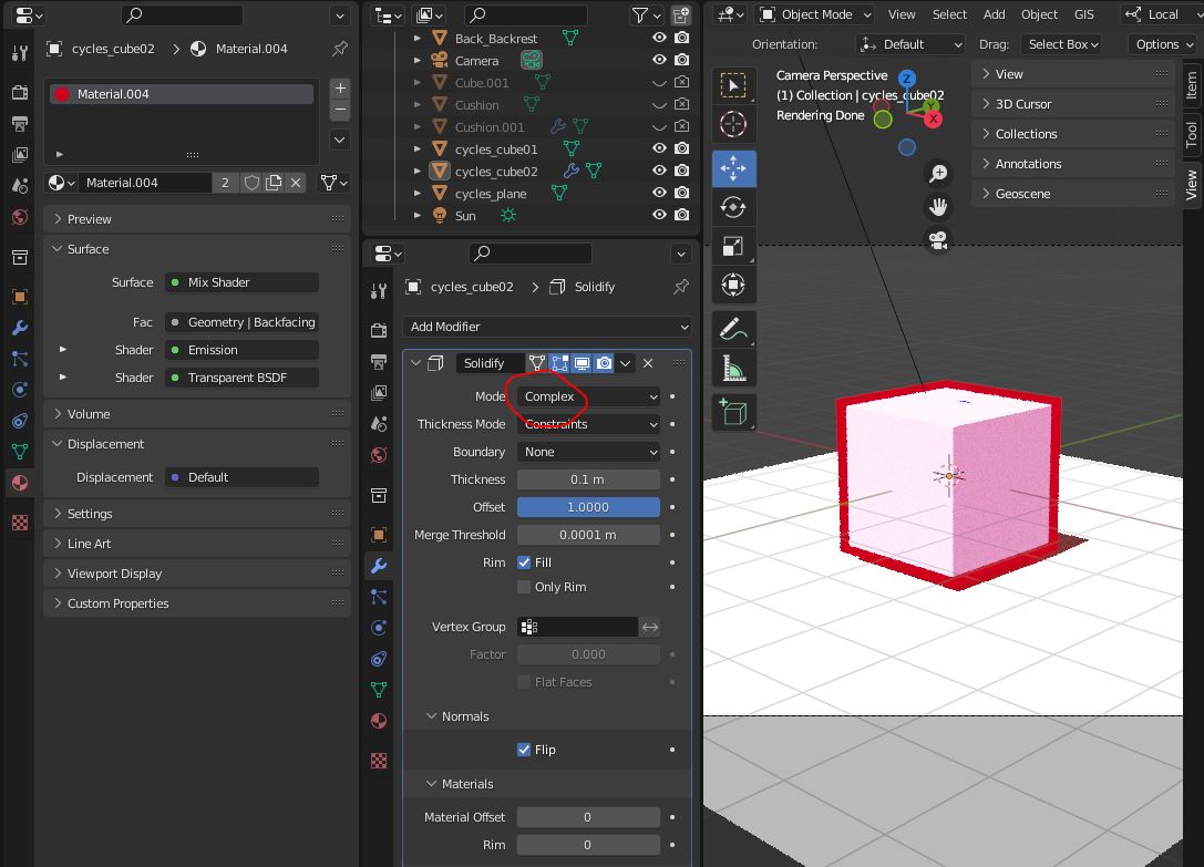
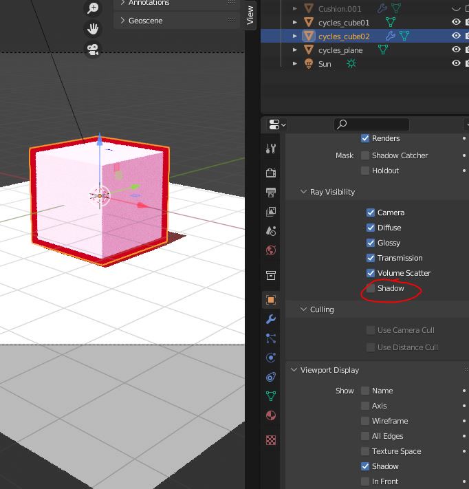
If you’re getting shadows cast onto your outline object, go to the ‘Object Properties’ tab in the Properties panel and, under Ray Visibility, untick ‘Shadow’. Cast shadows should still look ok because the outline object will be casting shadows. Self shadows might be affected – you may be able to come up with a compositing trick using a shadow catcher on the object.
Discussion: Why does this work? To understand, you need to know what a surface normal is. If you’re a CG-artist, you probably have an intuitive understanding of normals, whether you know it or not! The surface normal is the vector whose origin is any point on the plane defined by a particular polygon, and is perpendicular to the plane.
Recall a vector has a direction (and a magnitude). In this explanation we don’t care so much about the magnitude, but the direction tells the renderer which side of the face is ‘out’. So, when we flip the normals in the ‘Solidify’ modifier (or in Edit mode), we’re effectively turning the face is effectively “inside out”.
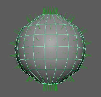
A piece of geometry with its normals displayed. Yes this is in Maya.
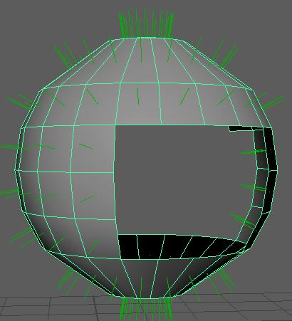
That same geometry with some of the faces on the right side flipped (I deleted some polys so it's easier to see the flipped normals)
A side note: You may be familiar with a “normal map”, which is a tool to ‘transfer’ high-resolution detail to a lower resolution model. If you’re a 3D arist, you’ll know that ‘resolution’ means more faces. But why does more faces mean more detail?
It means higher density information for the shader about how light should bounce off of the geometry. For components of the shader that deal with the surface normal, you’re limited to one normal per face (recall the above visuals – the surface normal is always perpendicular to the face). However, just as you can provide an albedo (color) map that allows the shader to use more than one color per face, you can provide a normal map that the shader to use more than one surface normal vector per face.
We need to flip the normals for two reasons. The first is so that everything blocking our original object is a backface, which we can then cull with the ‘Cull Backfaces’ tick box in the outline material. If you’re a CG artist, you’ll know that ‘backface culling’ basically means to tell the software not to render faces that aren’t facing the camera.
But what does ‘facing the camera’ mean in this context? Obviously it’s not z-depth related, as this technique of getting outlines shows.
It means that the angle between the camera’s view vector’s direction and the surface normal is less than 90 degrees. To be fair, this isn’t how the renderer actually finds out whether a face is facing the camera or not – the way they actually do it is by storing/going through the verts in a particular order (“winding order”). If the verts are out of winding order in camera space, the renderer knows the face has its back to the camera.
This video demonstrates what we're doing by flipping the normals and culling the backfaces. The white Suzanne has had the normals flipped and the backfaces culled, and the orange one has not. Notice how the white ones looks like it's essentially had every face that was towards the camera sliced off
A side note: the camera doesn’t actually have a single view vector. It has a number of view vectors – called camera rays – equal to the product of the resolution of the image plane. For example, the camera used to render a 1080p full HD image will have 1920 x 1080 = 2073600 camera rays.
The second reason to flip the normals is so that, once we’ve culled the backfaces, the revealed faces on the ‘inside’ of the model are facing the camera, which is probably really important for your shader.
This point is tautologically obvious, but it’s worth considering. If you’ve spent any time using 3D software, you’ve probably noticed that the ‘inside’/backfaces of a 3D model are usually rendered black. This isn’t a handy way to help you navigate your scene. A polygon’s surface normal facing away from the camera actually affects how the polygon is shaded.
For example, on a polygon shaded with Lambertian (aka ‘diffuse’) shading, the “brightness” of the rendered polygon is calculated using the cosine of the angle between the incoming light ray direction and the surface normal. Recall that the surface normal is always perpendicular to the face. On a non-transparent object, any incoming light ray always hits the face such that the angle between the ray and surface normal is less than 90 degrees.
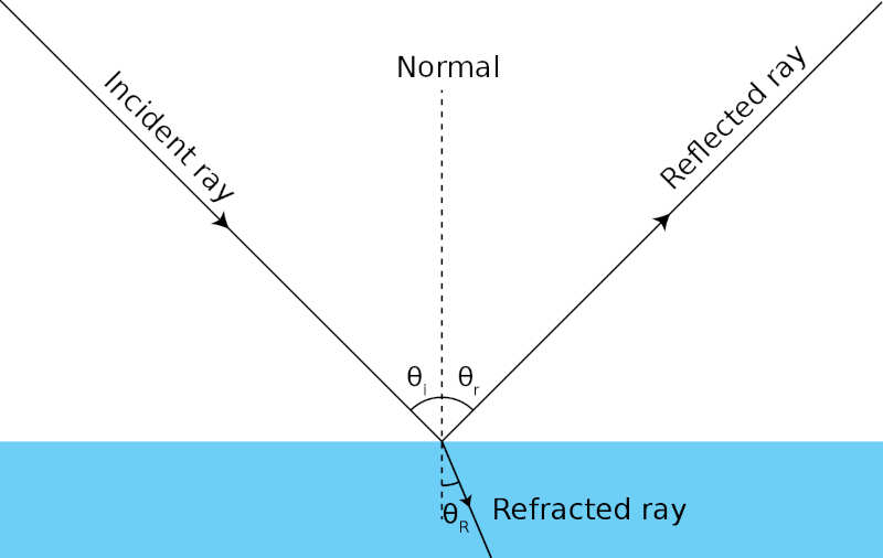
In this diagram, the blue section at the bottom corresponds to the polygon, the 'incident ray' is the incoming ray of light, and the 'normal' is the surface ray. It's self evident from looking at this diagram that theta(i) is less than 90 degrees.
Therefore when you invert the surface normal before calculating the intensity in the shader, you will get an angle greater than 90 degrees. Recall from high school geometry that the cosine of any angle greater than 90 degrees is negative. So, when you render a backface shaded with a Lambertian shader you’re guaranteeing that the brightness will be negative. This is the reason backfaces are often rendered black, no matter what.
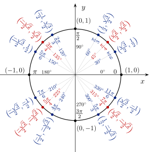
The x and y coords around the edge of the circle are cos and sin. Notice how on the left side of the circle (i.e. an angle greater than 90 degrees, cos in negative).
In our particular case, this business with the cosine doesn’t matter so much, since we’re using a Lambertian emission shader. With Lambertian emission, the brightness is constant no matter the angle at which the light rays hit it. It’s preferable if you don’t want shadows on your outline. But Lambertian shading is the most common lighting model in computer graphics, so it’s useful to think about.
Conclusion: That’s it! Hopefully you can use this technique in your own projects, and have a little bit deeper understanding of the graphics concepts behind it.